
Mesh partitioning#
Mesh partitioning in non-overlapping subdomains is realized by issuing a
mesh partitionner command in a ****mesher block and running Z-set in
mesher mode through the following command line:
> Zrun -m problem.inp
Z-set offers several partitioning engines which may be called through
the keyword **engine_split where engine stands for a
specific engine as described in split.
The most usual way to split a mesh according to a non overlapping domain
decomposition is to use a graph-based partitioning engine such
as **metis_split, which ensure an a priori optimal load balancing.
This type of engine works in two steps.
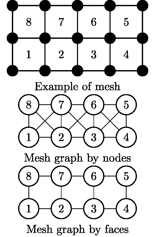
A graph representation of the inital mesh is build whith each element being a vertex of the graph. There are several approaches to define the edges. A simple one, can be enabled by the
*split_by_nodecommand, is to link two vertex as soon as the corresponding elements share a common node. This approach have some drawbacks as the partitioning does not guarantee to be free of internal mechanisms (such as elements linked by less than the required number of nodes to remain fixed to the rest of the domain) and may also lead to badly shaped subdomains (even if it can be checked and corrected a posteriori). An more robust approach is to link two vertex only whenever the corresponding elements share a common face. This is also called the dual graph of the mesh. This approach leads to subdomains usually more “compact” and avoid internal mechanisms whithout extra constraints on the graph splitting phase. This is the default behavior with all graph-based partitioning engines available in Z-set. The two previous way of defining a graph based on a given mesh are illustrated below.The graph is given as an argument to a graph partitioning engine which generate a coloring of the vertex, thus the elements. This coloring is choosen by a partitioning algorithm in order to ensure an equilibrated partition while minimizing the edgecut. To do so, Z-set is intefaced with some external libraries, such as METIS which is automatically called. Finally, this coloring is used as input to generate the subdomains decomposition as follow:
the subdomains meshes are generated and stored in a folder named
**problem-pmeshes;local cut files containing the global-local mapping and interface numbering are generated and stored in a folder
**problem-pcus;a global cut (
**problem.cu) file containing the splitting data common to all subdomains is also generated.
When a computation use external parameters or boundary conditions
inputed as external files, those files have also to be splitted
according to the domain decomposition. For a parameter binary file used
with the ***parameter **file/ command, this can be achieved by the
**build_parallel_param_files mesher command described in
param_files. For a binary file
based boundary condition (see the ***pressure) command
in the user manual, this can be done with the
**build_parallel_boundary_files on
boundary_files.
Note
On large meshes, it is strongly advised to use the mesh binary format
(.geo) instead of the ASCII one (.geof) as it dramatically
improve the reading and writing phases and also more efficient regarding
the size of the resulting files. The example below show how to convert
an ASCII mesh (**problem.geof) into its binary
counterpart.
****mesher
 ***mesh problem.geo
  **open problem.geof
****return
Example#
The example below show how to split an initial mesh into 96 subdomains
using the METIS split engine, and to split the 5 maps of the
temperature.node (used as an external parameter) likewise. Note that
the corresponding command **build_parallel_param_files has to be run
after the mesh splitting. The command **dont_save_final_mesh avoid
to save again the monolithic input mesh at the end of partitionning to
save time. Be aware that the additional element set showing the domains
won’t then be saved in the input mesh after splitting.
****mesher
 ***mesh problem.geo
  **open problem.geo
  **metis_split
   *domains 96
  **build_parallel_param_files
   *file temperature.node
   *card 5
  **dont_save_final_mesh
****return