
Z-mat Forge interface#
Description#
The Zforge interface enables the use of Z-mat material laws within Forge simulations. This section introduces the Zforge interface. Note that this interface bears a strong resemblance to the existing interface of Z-mat for ABAQUS, hence interested users can refer to the relevant documentation for an exhaustive overview.
Syntax#
To launch the simulation called problem.ref:
\(~\,~\,~\,~\,\)
% Zforge[ opts ] *problem \(\hookleftarrow\)To print the help for the command
Zforge\(~\,~\,~\,~\,\)
% Zforge-help \(\hookleftarrow\)
Getting started#
Note
The interface is built for Forge versions \(>=\) 4.0
Ensure both the Z-set and Forge simulation software suites are installed. Setup the environment variables
Z7PATHandFORGE_ROOTpointing to the respective installation directories.As a preliminary step to launch a Forge simulation using a Z-mat law, a user solver including the Z-mat/Forge library file must be registered as a new solver.
Click on Computation manager \(\longrightarrow\) Define user solver
Create a new user solver (or select an existing one), then specify the path to the user subroutine:
$Z7PATH/Zforge/tsv_mf2userroutines.sofor 2D case, or$Z7PATH/Zforge/tsv_mf3userroutines.sofor 3D case (*.dll for Windows). You should also specify the path to the Forge solver (note that this path may change between Forge versions).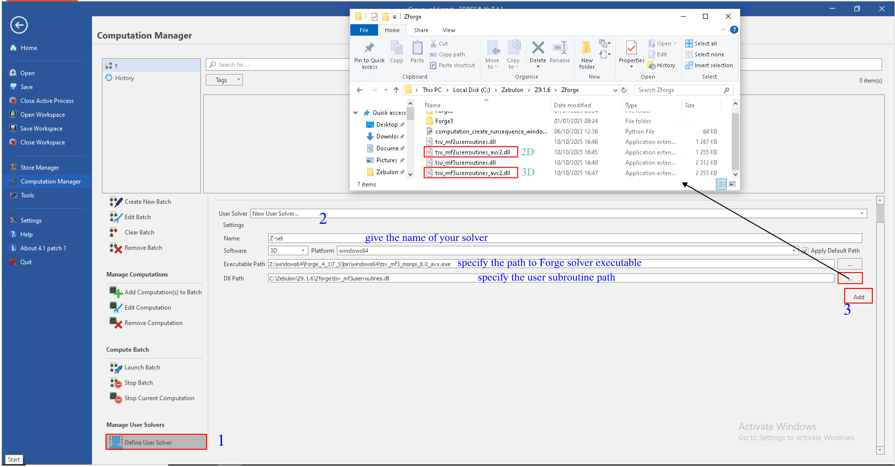
Click on Add to save the new user solver.
Now a simulation using Z-mat/Forge interface can be launched in two ways:
using Zforge script (as shown above).
from the NxTGUI platform (Forge graphical interface)
Compatible Z-mat behaviors#
Forge’s FE solver uses the stabilized bubble finite element. This
element is used to solve the Stock’s problem, where the unknowns are the
velocity \(v\) and the pressure \(p\). When it comes to material
integration using this type of element, the deviatoric stress and the
hydrostatic stress are integrated independently. For this reason, only
material behaviors for which the plastic deformation only depends the
deviatoric stress tensor can be used in the Z-mat/Forge interface. For
example, in the gen_evp assembly, the plasticity criteria
that depend on the hydrostatic pressure (trace of the stress
tensor) are not supported (e.g. unsym, cast_iron,
tensile_mises, gurson, linear_drucker_prager, etc.). In
addition, the integration of the hydrostatic stress assumes an isotropic
elasticity, therefore only isotropic elasticity is supported in the
Z-mat/Forge interface.
Input file changes#
When a Z-mat file is created through the NxTGUI interface, the TMF file including the required blocks and state variables necessary to the materiel integration is generated automatically.
Similar to other Z-mat interfaces, there are some lines in the user’s
input deck (the .ref file or .tmf file) that are modified to indicate that a
user–material is being used, and to specify the number of state variables for storage.
The syntax is dimension specific (2D/3D). For Forge 2D, the only modification is under the
block .RHEOLOGIE, the Z-mat file is indicated as:
Thermoecroui:ZMAT:FILE=Z-mat file. Additional storage necessary
for the associated state variables is allocated automatically. For Forge
3D, the Z-mat material file is indicated under the block
.RHEOLOGIE, as follows: LOIV RHEO Z-mat file. Also, all
state variables necessary for the material integration are added as
shown in the following example.
For instance, for the following Z-mat material file:
***behavior gen_evp auto_step
 **elasticity isotropic
   young 1.105E+05
   poisson 0.3
 **potential gen_evp ep
  *flow norton
   K 75.0
   n 12.93
  *isotropic nonlinear
   R0 848.895020
   Q -3.20E+02
   b 120.0
  *kinematic nonlinear
   D 120.
   C 47280.
***return
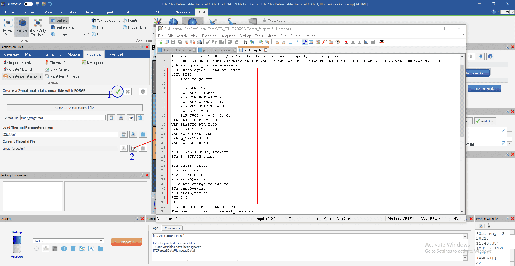
The changes to the .RHEOLOGIE block of the .tmf
file are presented below:
LOIV RHEO Z-mat_file_name
ETA STRESSTENSOR(6)=0.D0,0.D0,0.D0,0.D0,0.D0,0.D0
ETA EQ_STRAIN=0.D0
ETA eel(6)=0.D0,0.D0,0.D0,0.D0,0.D0,0.D0
ETA epcum=0.D0
ETA al1(6)=0.D0,0.D0,0.D0,0.D0,0.D0,0.D0
ETA epi(6)=0.D0,0.D0,0.D0,0.D0,0.D0,0.D0
ETA temp0=0.D0
ETA eto(6)=0.D0,0.D0,0.D0,0.D0,0.D0,0.D0
This block of commands can be generated using Zpreload utility, as follows:
\(~\,~\,\) % Zpreload Z-mat_file_name\(\hookleftarrow\)
Note, that for both Forge 2D and Forge 3D, the length of the Z-mat file name must not exceed 12 characters.
Export Forge Database into Z-set format#
It is possible, using the Z-set result management functions for Forge (as described in the Z-set User Manual), to merge separate Forge results files (
.fg3or.fg2) in a unique Z-set database (i.e., for further visualization or post-processing purposes):\(Z7\) database format: uses a single mesh (the initial mesh), onto which all maps are projected.
\(Z8\) database format: stores results on the different meshes (due to remeshing) generated during the simulation.
For example,
% input file export.inp
% to be run using: Zrun export.inp

****forge
 ***prefix billet
 ***output Database_Billet_Zmat
 ***format fg3
 ***write_z8
****return
Convert Forge Database into Z-set formats through NxtGUI:
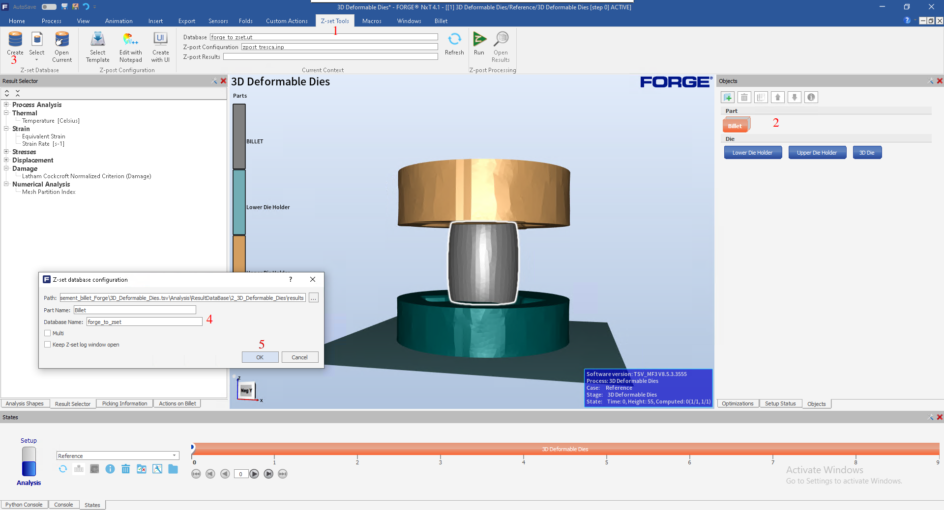
Go to Z-set tools
Select the component whose results you want to translate to Z7 format.
Click Create.
Enter the name of translated database.
Click OK to confirm.
Zmaster interface#
The results of the Z-mat/Forge simulation are stored in files with
extension .fg3 (for 3D simulations) and .fg2 (for 2D
simulations). Let us consider an example provided with Z-set software
distribution, in the following directory :
$Z7PATH/TESTS/Zforge_test/INP/Zforge_3D/
The resulting files produced in this simulation will be stored in :
$Z7PATH/TESTS/Zforge_test/INP/Analysis/ResultDataBase/Zforge_3D/results/
For each increment \(\%t\), there is \(\%n\) .fg3 file,
where \(\%n\) is the number of processors used for computation.
These .fg3 files can be visualized individually using Zmaster GUI,
as follows:
% Zmaster problem_%nd%t.fg3\(\hookleftarrow\)
As shown above, Forge results can also be exported to a single Z-set results database and visualized using the Zmaster interface.